
Pocket Watch Parts — Complete Illustrated Guide
A mechanical pocket watch is one of the most intricate portable mechanisms ever devised. Dozens of precisely engineered components work together across four interconnected systems: the case and dial, the power and gear train, the escapement and balance wheel, and the motion and calendar works. This guide names and describes every part visible in the diagrams below, then explains in detail how each system functions and how the parts interact.
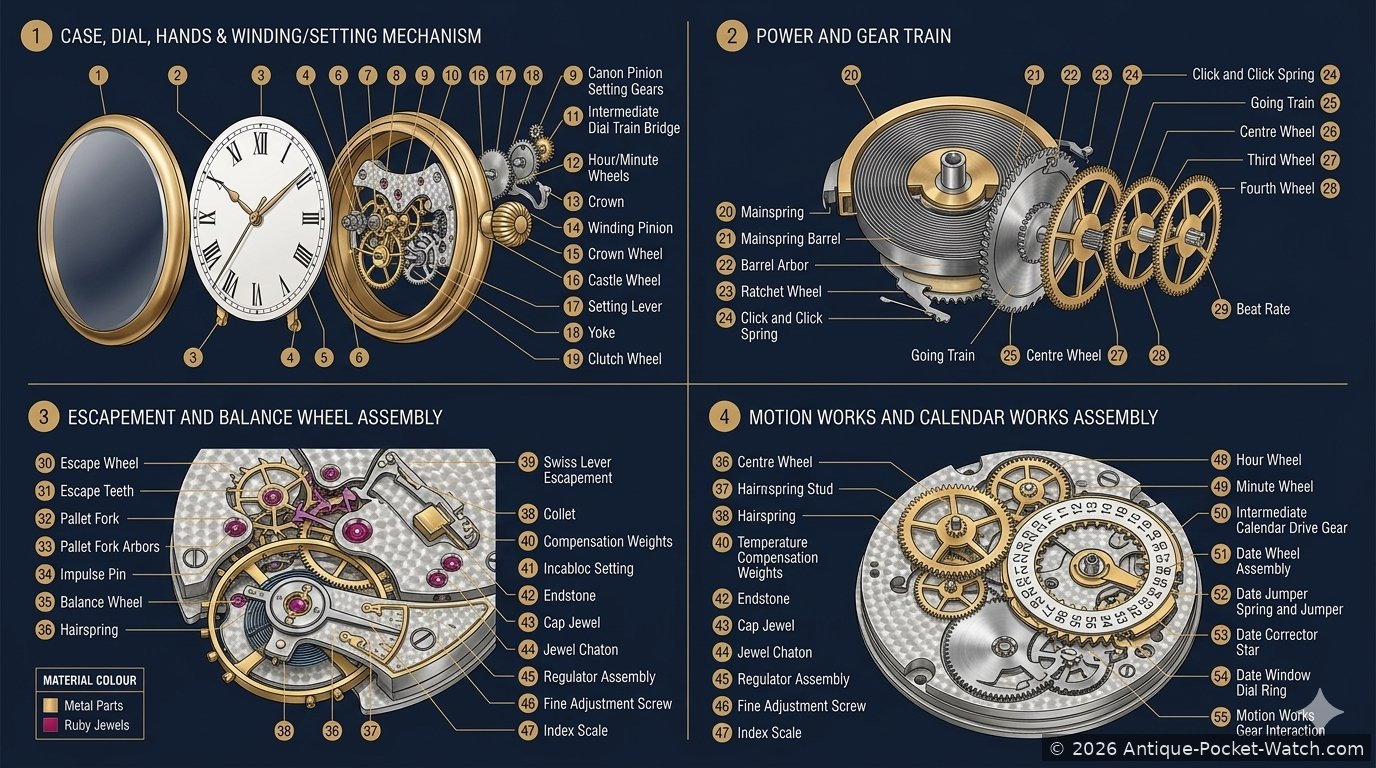
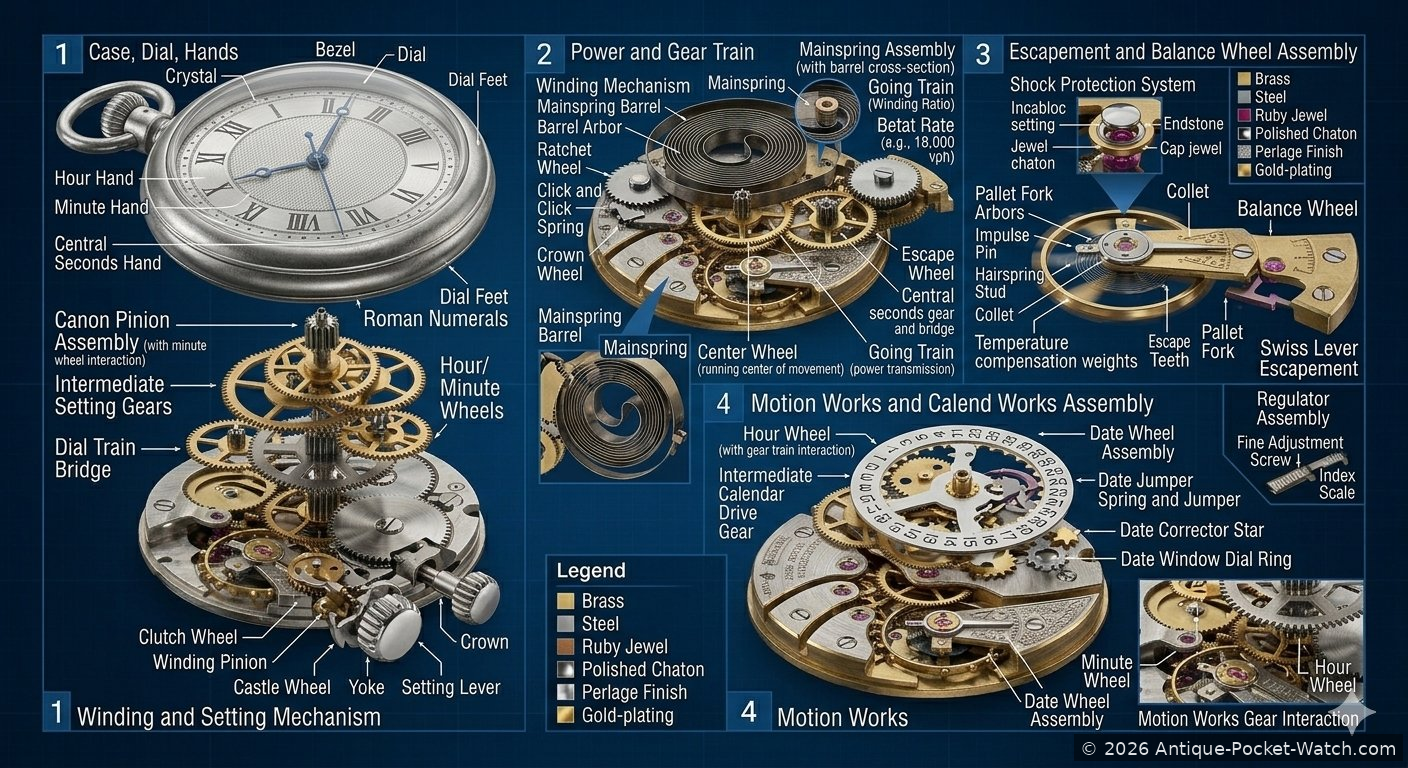
Case, Dial, Hands & Winding and Setting Mechanism
- 1.BezelThe ring that surrounds and retains the crystal. On antique watches it is often hinged or snap-fit; on modern pocket watches it may be threaded or press-fit.
- 2.CrystalThe transparent cover over the dial, historically made from rock crystal or mineral glass, and on later watches from synthetic sapphire or acrylic.
- 3.DialThe face of the watch, typically white enamel or silvered metal, carrying the hour and minute markings and any subsidiary dials.
- 4.Dial FeetTwo small posts soldered to the back of the dial that locate and secure it to the movement plate.
- 5.Roman NumeralsHour markers applied to or printed on the dial. Traditional pocket watches use Roman numerals; railroad-grade watches typically use bold Arabic numerals for legibility.
- 6.Hour HandThe shorter hand, driven by the motion works to complete one revolution every 12 hours.
- 7.Minute HandThe longer hand, driven directly by the cannon pinion to complete one revolution per hour.
- 8.Central Seconds HandA seconds hand mounted at the centre of the dial, driven off the fourth wheel of the going train at one revolution per minute.
- 9.Canon Pinion AssemblyA friction-fit tubular pinion pressed onto the centre wheel arbor. The cannon pinion drives the minute hand and, via the motion works, the hour hand. Its friction fit allows time-setting without stopping the movement.
- 10.Intermediate Setting GearsA small train of gears that transmits the setting motion from the winding stem to the cannon pinion when the crown is pulled out to the setting position.
- 11.Dial Train BridgeA plate or bridge on the dial side of the movement that supports the arbors of the motion works and setting gear train.
- 12.Hour/Minute WheelsThe motion works wheels that reduce the rotation of the cannon pinion by 12:1 to drive the hour hand at the correct rate.
- 13.CrownThe externally accessible knurled knob at the top of the case used to wind the mainspring and, when pulled out, to set the time.
- 14.Winding PinionThe small pinion connected to the crown stem that engages the ratchet wheel when the crown is pushed in, transmitting winding torque to the barrel.
- 15.Crown WheelIn the winding train, the crown wheel (also called the ratchet click wheel) meshes with the winding pinion to transfer crown rotation into the barrel ratchet system.
- 16.Castle WheelA wheel with axially projecting teeth (resembling castle battlements) that engages the setting lever when the crown is pulled out, switching the stem from winding mode to setting mode.
- 17.Setting LeverA sprung lever that detects whether the crown stem is pushed in (winding position) or pulled out (setting position), and routes torque accordingly.
- 18.YokeA rocking lever that works with the setting lever to shift the sliding pinion between the winding and setting gear trains.
- 19.Clutch WheelA sliding pinion on the stem that, depending on crown position, engages either the winding train or the setting train.
How Section 1 Works Together
When the crown is pushed in, the clutch wheel engages the winding train. Rotating the crown turns the winding pinion, which drives the crown wheel and ratchet wheel, winding the mainspring inside the barrel. A click spring prevents the ratchet from unwinding when winding pressure is released.
When the crown is pulled out, the setting lever and yoke slide the clutch wheel to engage the setting train instead. Crown rotation now passes through the intermediate setting gears to the cannon pinion, moving the minute and hour hands. Because the cannon pinion is friction-fit on the centre wheel arbor, the hands can be moved independently of the running movement without stopping it.
The dial and hands form the user interface of this system. The cannon pinion drives the minute hand directly and simultaneously drives the motion works — a small reduction gear pair (the minute wheel and hour wheel) that turns the hour hand at one-twelfth the speed of the minute hand, completing one revolution every 12 hours.
Power and Gear Train
- 20.MainspringA long ribbon of hardened steel coiled inside the barrel. When wound, it stores potential energy; as it uncoils it releases that energy to drive the entire movement.
- 21.Mainspring BarrelA cylindrical brass container enclosing the mainspring. The outer wall of the barrel is toothed and acts as the first wheel of the going train.
- 22.Barrel ArborThe central spindle of the barrel, to which the inner end of the mainspring is attached. The arbor is driven by the ratchet wheel when the watch is wound.
- 23.Winding Mechanism / Ratchet WheelA toothed wheel fixed to the barrel arbor, engaged by the winding click. It allows the arbor to be turned in one direction only, preventing the mainspring from unwinding during winding.
- 24.Click and Click SpringThe click is a small pivoted pawl that engages the ratchet wheel teeth; the click spring holds it in engagement. Together they form a one-way locking mechanism.
- 25.Going TrainThe series of wheels and pinions — centre wheel, third wheel, fourth wheel, and escape wheel — that transmit energy from the barrel to the escapement at progressively reduced torque and increased speed.
- 26.Centre WheelThe first wheel of the going train, driven by the barrel. Its arbor carries the cannon pinion and completes one revolution per hour.
- 27.Third WheelDriven by the centre wheel pinion; an intermediate transmission wheel with no direct external function other than transmitting power down the train.
- 28.Fourth WheelCompletes one revolution per minute and typically carries the seconds hand arbor. Its pinion drives the escape wheel.
- 29.Beat RateThe number of escapement beats (oscillations) per hour, typically 18,000 vph (vibrations per hour) for a traditional pocket watch — equating to 5 beats per second, or 2.5 Hz.
How Section 2 Works Together
The mainspring is the sole energy source of the movement. As it uncoils from the wound position, it rotates the barrel wall. Because the barrel wall is toothed, it drives the first pinion of the going train — the centre wheel pinion. Each successive wheel in the train has more teeth than the pinion it drives, creating a series of speed increases accompanied by proportional torque reductions.
By the time energy reaches the escape wheel at the end of the train, the rotational speed is very high but the torque is very low — precisely what is needed to interact with the lightweight, fast-oscillating balance wheel. The centre wheel rotates once per hour, the fourth wheel once per minute, and the escape wheel advances one tooth per beat of the balance wheel.
Without the escapement to regulate it, the fully wound mainspring would drive the gear train to a standstill in seconds. The escapement acts as a controlled release valve, allowing the train to advance only one tooth at a time in synchrony with the balance wheel’s oscillations — this is what makes the watch keep time.
Escapement and Balance Wheel Assembly
- 30.Escape WheelThe final wheel of the going train, with specially shaped teeth that interact with the pallet fork. It advances one tooth per beat of the balance wheel.
- 31.Escape TeethThe precisely angled teeth of the escape wheel. In a Swiss lever escapement these have a club-tooth profile; the geometry of each tooth controls the impulse and locking action.
- 32.Pallet ForkA fork-shaped lever pivoting between two banking pins, with two pallet stones that alternately lock and release the escape wheel teeth. It is the central component of the escapement.
- 33.Pallet Fork ArborsThe pivot points on which the pallet fork rocks back and forth as each tooth of the escape wheel is released and caught.
- 34.Impulse PinA small ruby or steel pin set into the roller table on the balance wheel staff. It enters the notch of the pallet fork once per oscillation to transmit a brief push (impulse) to the balance wheel.
- 35.Balance WheelThe oscillating controller of the movement. A weighted wheel that rotates back and forth about its staff under the control of the hairspring. Its regularity of oscillation governs the timekeeping of the entire watch.
- 36.Hairspring (Spiral Spring)An extremely fine flat spiral spring attached at its inner end to the balance staff and at its outer end to the balance cock. It provides the restoring force that returns the balance wheel to its centre position after each oscillation.
- 37.Hairspring StudThe fixed pin to which the outer end of the hairspring is anchored on the balance cock or a separate stud carrier.
- 38.ColletA small brass collar that clamps the inner end of the hairspring to the balance staff. Also used to describe the jewel settings in some contexts.
- 39.Swiss Lever EscapementThe most widely used escapement in pocket watches from the late 19th century onwards. It combines safety against accidental unlocking (via the safety action between the dart/guard pin and the roller) with efficient impulse transmission.
- 40.Temperature Compensation WeightsBimetallic or adjustable weights on the balance wheel rim that shift outward as temperature rises (counteracting the weakening of the hairspring) and inward as temperature falls. Found on high-grade railroad and observatory watches.
- 41.Incabloc SettingA shock-absorbing jewel mounting system that allows the balance staff pivot jewels to deflect under impact and spring back, protecting the delicate pivots from breakage.
- 42.EndstoneA flat jewel (usually synthetic ruby) that forms the end cap for the balance staff pivot. It limits end-shake and reduces friction at the tip of the staff.
- 43.Cap JewelAnother term for the endstone, particularly when describing the jewel that caps the pivot hole jewel in the jewel setting stack.
- 44.Jewel ChatonThe polished brass ring or setting in which a pivot hole jewel is mounted. On high-grade movements chatons are screwed or pressed into the plates for precise positioning.
- 45.Regulator AssemblyA device for fine-tuning the rate of the watch by altering the effective length of the hairspring. A small index lever (the regulator) slides along the hairspring between two pins called curb pins.
- 46.Fine Adjustment ScrewA micrometric screw on precision regulators that allows very small incremental adjustments to the regulator position without moving it by hand.
- 47.Index ScaleA graduated arc engraved on the balance cock or regulator plate, marked Fast (F) and Slow (S), against which the regulator pointer is read when adjusting the rate.
How Section 3 Works Together
The escapement is the heart of timekeeping. The balance wheel oscillates back and forth at a fixed frequency determined by its moment of inertia and the stiffness of the hairspring — in a typical pocket watch, 2.5 oscillations per second (18,000 vph). Each half-oscillation constitutes one beat.
As the balance wheel swings in one direction, the impulse pin on its roller engages the notch of the pallet fork and pushes it across. This motion unlocks one tooth of the escape wheel (the exit pallet stone releases its tooth) while simultaneously locking the next tooth on the entry pallet stone. As the newly released tooth slides across the exit stone, it gives the pallet fork — and through it the balance wheel — a brief push called the impulse. This replaces the energy the balance wheel loses to friction on each oscillation, keeping it swinging at constant amplitude.
The hairspring continually returns the balance wheel to centre. As the wheel reverses direction, the process repeats in mirror image: the entry pallet stone releases, the exit stone locks, and the impulse pin receives another push from the opposite side. The result is the characteristic tick-tock of a mechanical watch — each ‘tick’ and ‘tock’ representing one tooth of the escape wheel being released.
The regulator adjusts timekeeping by moving two curb pins along the hairspring, changing its effective free length. Moving the regulator toward Fast shortens the active length of the spring, increasing its restoring force and making the balance oscillate faster. Moving it toward Slow lengthens the spring, slowing the oscillation. On high-grade railroad watches this adjustment is made with a micrometric screw to achieve accuracy within 30 seconds per day — a legal requirement for railroad service.
Temperature compensation weights counteract the effect of thermal expansion on the balance and the stiffness changes in the hairspring, maintaining a consistent beat rate across a range of temperatures.
Motion Works and Calendar Works Assembly
- 48.Hour WheelThe wheel that carries the hour hand pipe and completes one revolution every 12 hours. It is driven by the minute wheel at a 12:1 reduction from the cannon pinion.
- 49.Minute WheelAn intermediate wheel in the motion works that meshes between the cannon pinion and the hour wheel, providing the 12:1 speed reduction needed to drive the hour hand correctly.
- 50.Intermediate Calendar Drive GearA wheel that takes rotation from the motion works (typically from the hour wheel) and transmits it to the calendar mechanism, advancing the date display once every 24 hours.
- 51.Date Wheel AssemblyA ring or disc bearing the date numerals (1–31), driven by the calendar mechanism to advance by one position each day at midnight.
- 52.Date Jumper Spring and JumperA spring-loaded lever that holds the date wheel in precise indexed positions (one per date number) and produces the crisp snap of the date change. It also prevents the date wheel from drifting between positions.
- 53.Date Corrector StarA star-shaped wheel (often 31-pointed, one per day of the month) that is advanced by a finger or cam on the calendar drive, stepping the date wheel forward by exactly one day at a time.
- 54.Date Window Dial RingAn aperture or window cut in the dial through which the current date numeral on the date wheel is visible. It frames the date display and masks the adjacent numerals.
- 55.Motion Works Gear InteractionThe collective term for the meshing of the cannon pinion, minute wheel, and hour wheel that together constitute the motion works — the sub-system responsible for driving the hour and minute hands at their correct relative speeds.
How Section 4 Works Together
The motion works is the speed-reduction stage between the going train and the hands. The centre wheel arbor — which completes one revolution per hour — carries the cannon pinion. This pinion drives the minute wheel, which in turn drives the hour wheel. The gear ratio between the cannon pinion and hour wheel is 12:1, so the hour wheel completes one revolution for every 12 revolutions of the cannon pinion — once every 12 hours. The minute hand is fixed to the cannon pinion and the hour hand to the hour wheel pipe, giving the correct relative motion between them.
In watches equipped with a calendar mechanism, a further reduction drives the date display. The hour wheel (or a dedicated calendar drive wheel) carries a 24-hour finger or cam that advances the date corrector star by one tooth every 24 hours — at or around midnight. Each tooth of the corrector star represents one day; when the finger pushes the star forward one tooth, the date wheel (connected to the corrector star) advances by one numeral.
The date jumper spring keeps the date wheel firmly located between advances, ensuring the date numeral always appears centred in the dial window. Without it the date wheel could drift to show a partial numeral. At the end of months with fewer than 31 days, most simple calendar mechanisms must be corrected manually by pressing a date corrector button or using the crown — a limitation of the basic calendar design that more complex annual and perpetual calendar mechanisms overcome through additional levers and programme wheels.
On a watch with a central seconds hand, the fourth wheel (completing one revolution per minute) carries a seconds hand arbor that protrudes through the dial centre alongside the cannon pinion pipe and hour wheel pipe — a concentric stack of three independently rotating tubes delivering the three hands to the dial from a single central axis.
Complete Parts Reference — Numbered List
All parts identified in the diagram, numbered for reference:
- Bezel
- Crystal
- Dial
- Dial Feet
- Roman Numerals
- Hour Hand
- Minute Hand
- Central Seconds Hand
- Canon Pinion Assembly
- Intermediate Setting Gears
- Dial Train Bridge
- Hour / Minute Wheels
- Crown
- Winding Pinion
- Crown Wheel
- Castle Wheel
- Setting Lever
- Yoke
- Clutch Wheel
- Mainspring
- Mainspring Barrel
- Barrel Arbor
- Ratchet Wheel
- Click and Click Spring
- Going Train
- Centre Wheel
- Third Wheel
- Fourth Wheel
- Beat Rate (18,000 vph)
- Escape Wheel
- Escape Teeth
- Pallet Fork
- Pallet Fork Arbors
- Impulse Pin
- Balance Wheel
- Hairspring
- Hairspring Stud
- Collet
- Swiss Lever Escapement
- Temperature Compensation Weights
- Incabloc Setting
- Endstone
- Cap Jewel
- Jewel Chaton
- Regulator Assembly
- Fine Adjustment Screw
- Index Scale
- Hour Wheel
- Minute Wheel
- Intermediate Calendar Drive Gear
- Date Wheel Assembly
- Date Jumper Spring and Jumper
- Date Corrector Star
- Date Window Dial Ring
- Motion Works Gear Interaction
See also: Pocket Watch Parts A–Z — Repair Guide — Case Types & Materials